Installation Advice & Information
The basic principles of effective ceiling loudspeaker installation
The first priority of any sound reproduction system is providing listeners with a level of clear, intelligible sound higher than any possible background noise (at least 6dB in the case of paging systems), together with a wide frequency response and uniform sound pressure level over the area to be covered. To meet these criteria, the hypothetically ideal solution would be to place a single sound source at an equal distance from all required listening positions. As this is all but impossible to achieve in most environments, some compromises usually have to be made. The purpose of these notes is to provide some basic advice as to how this might be accomplished.
Ceiling-mounted loudspeakers
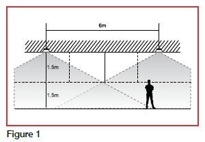
In environments offering a suitable ceiling construction and height, the best results canoften be obtained by utilising loudspeakers mounted in the ceiling structure. Once the most suitable loudspeaker type has been chosen and its dispersion at the required mounting height ascertained, the number of units needed to obtain constant and uniform coverage and sound pressure level (SPL) can be established.
Remember, when calculating the SPL it is the level at the listeners’ ears to be considered, not the level at the loudspeaker or floor level.
The required speaker quantity is calculated by dividing the floor area to be covered by the area covered by a single loudspeaker. Note; to obtain even coverage, a suitable overlap between adjacent loudspeakers is required.
Wall-mounted loudspeakers
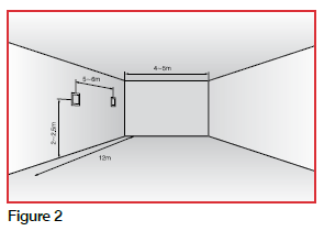
If the architectural features of the room are not compatible with ceiling-mounted loudspeakers or if a wall-mounted solution is preferred, it is essential to observe a few basic rules to obtain the most effective sound distribution. In order to maintain the most efficient listening point inside the direct signal area, both in-wall and surface mounted loudspeakers with power from 6W to 20W should be installed at a height between 2 and 2.5m.
The maximum distance between adjacent loudspeakers must be no more than 5 ~ 6 metres along the length of the room, where the room is no wider than 4 ~ 5 metres.
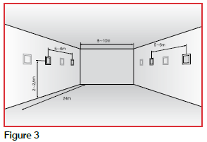
For wider rooms (eg. 8 ~ 10 metres), it is recommended to install loudspeakers in an alternate pattern along both opposite walls, to provide adequate coverage and maintain sound pressure at the best possible constant level throughout the area for coverage.
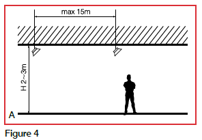
High ambient noise level environments
For effective sound distribution in locations with high levels of ambientnoise,horn loudspeakers are often specified as theyproduce higher sound pressure levels and, therefore, increased audibility in such conditions. However, it should be noted that horn loudspeakers driven by pressure units are not usually suitable for use on systems where music is required, as the frequency response is optimised for voice reproduction.
Where higher quality sound and/or music reproduction is a requirement, ‘Sound Projectors’ can often be used as an alternative, though, as they generally produce a lower SPL, a larger number is likely to be required to cover the same area.
In all cases these speakers should be installed at a maximum distance of 15m from one another.
They should all be mounted in the same direction with care taken to ensure they are all wired in phase.
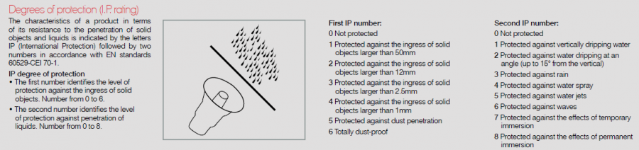
Degrees of protection (I.P. rating)
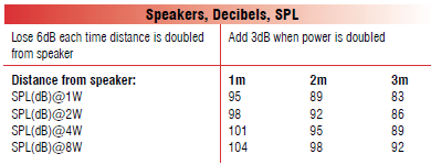
Speakers, Decibels, SPL
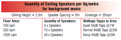
Quantity of Ceiling Speakers per Sq/metre for background music
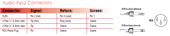
Audio Input Connectors
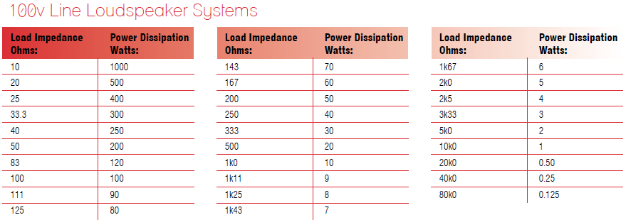
100v Line Loudspeaker Systems
Low Impedance and 100v Line Systems
A Low Impedance system is normally only used where a small number of loudspeakers are required, to be placed only a short distance from the amplifier.
The constant voltage system (ie.100v line ) offers a host of advantages on systems of all sizes particularly where long speaker cable runs are required. This connection system requires each loudspeaker to be equipped with its own line transformer which converts the low impedance of the loudspeaker to the much higher impedance of the line itself. The current flow on a line at 100v is considerably lower than that at low impedance. Consequently the voltage drop along the line is much lower which, in turn, means a smaller gauge of cable can be used.
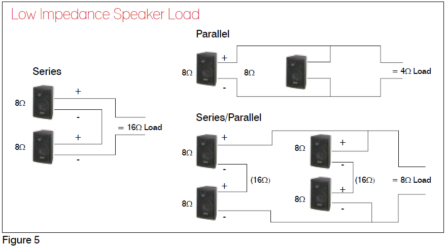
With installations operating at low impedance, the total load series and/or parallel presented to the amplifier must be greater than the minimum impedance the amplifier is rated to drive (see Figure 5). The power output of the amplifier at the selected impedance should be equal to or less than the power the load can withstand. Beware – it is possible to destroy loudspeakers if the amplifier feeding them is overdriven to the point of clipping.
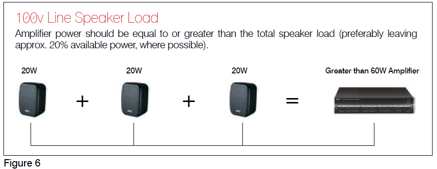
Where the constant voltage (100v line) system is utilised, the total load is calculated by adding the wattage setting of each loudspeaker on the system together. The resulting figure is the total wattage load that will be applied to the amplifier; it follows, therefore, that the output of the amplifier used must be greater than this figure (see Figure 6).
Some basic rules which must always be observed
Input Signals
• All microphone inputs must be wired as balanced circuits using good quality twin twisted pair microphone cable with an overall screen; input connectors must have 3 pins and the amplifier inputs configured as balanced. The same principal should also be applied to line inputs where the cable is long enough to pick up interference.
• Note, the signal return wire and the screen of the cable must be separate from the source to the input of the amplifier. If they are connected together at any point, or the cable used has only a single screened core, it is impossible for a circuit wired in this manner to operate as a balanced line.
• A line connected incorrectly is wide open to interference pickup and hum which is all but impossible to cure by any method short of re-wiring.
Loudspeaker Networks
• As the current flow in low impedance speaker circuits is much higher, it follows that larger cables will be required; the absolute minimum size required is 1mm twin with 1.5mm or even 2.5mm being a better choice for even quite short runs.
• With 100v Line Systems it is sometimes possible to use 0.75mm twin on small systems, though 1mm or 1.5mm is a better choice.
• If attenuators (volume controls) are to be used, this can alter the cable requirements – please seek advice before commencing the installation.
• Under no circumstances use screened cable on loudspeaker networks as serious damage to power amplifiers can be caused.
Amplifier Selection
The function of an amplifier is to raise the level of sound sources such as microphones, radio tuners, CD players, etc. to a level capable of driving the loudspeaker network. Most amplifiers have several inputs to allow various sources to be mixed and prioritised to suit the requirements of specific installations.
When selecting a suitable amplifier power, it is essential to allow some headroom for both future expansion and load variations – a figure of 20% is desirable with typical 100v systems
(see Figure 6 above).
MAJORCOM
Expert in Public Address and Voice Alarm systems for the past 50 years.
Our other documentation
Acoustic basics (Fundamentals)

A sound is a pressure variation around the atmospheric pressure expressed in Pascal (Pa). Human ear is sensitive from 20µPa to 200Pa. A sound wave is …
EN 54-24 standard requirements
Connection of the power is to be performed within the speaker. We should not have direct access to various settings …
Acoustics basics (PA calculation use-case)
For example, a outside space. This outdoor area is 10m wide and 32m long. The background of this space is 65 dB…