
Electronic wiring
Audio signals
Balanced Vs Unbalanced Audio
Which way do we go ?
This is a good question, of which the answer lies in a couple of other questions, listed below. The obvious answer is which ever method gets you the clearest audio. Because the main goal of a sound system is to reproduce the original sound in the best and clearest way possible.
1. What is unbalanced audio ?
2. What is balanced audio ?
3. What device are you coming out of? And what device are you going into ?
4. What is the distance between the devices ?
Let’s answer some of those questions and then go from there.
What is Unbalanced Audio ?
Unbalanced audio is what will be found in the typical home stereo. The typical connector for unbalanced audio is either RCA, 1/4″ TS (Tip, Sleeve), and 1/8″ TS. Another variant connector is the stereo wired TRS (Tip, Ring, Sleeve) connectors, be sure to not confuse these with a Balanced Audio cable, as they look a lot alike.
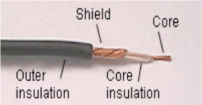
The Unbalanced cable uses a single center conductor, and the shield, for the audio signal to travel on. Audio travels on the shield of the cable, which means that any interference that the shield picks up, will be inserted on the audio signal. This could come across in any number of audible ways, from hums to radio stations.
What is balanced audio ?
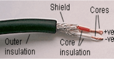
Balanced audio is a method of interconnecting audio equipment using impedance balanced lines. Balanced Audio uses a cable made up of two conductors that are twisted together and surrounded by an overall shield. The basic idea being that each conductor is connected to an impedance at each end of the line. The impedances are the same between both conductors, even if they are different at each end of the line. The audio on the two conductors is exactly the same, except that one of the conductors has the audio inverted at the source piece of equipment. The input of the destination equipment inverts the inverted audio and sums the two channels together. The shield of the cable is never part of the audio signal path and should be grounded directly to the frame of the audio equipment.
The shield of the cable is the first line of defense, so to speak. The interference should be picked by the shield and then deposited to the electrical ground of the system, hopefully never becoming part of the audio signal.
The twists in the audio cable help to defer electromagnetic signals. An electromagnetic interference signal is actually picked up equally by both conductors and actually travels to the destination piece of audio equipment. This is were we go back to High School Physics classes.
The Interference produces an addition to the original signal, let’s say a positive 4 on an imaginary graph, on both conductors. When the destination equipment then inverts one of the conductors, the interference is now a positive 4, on conductor #1 and a negative 4 on conductor #2. When these are summed together they come out to zero. There by removing the interference from the audio signal. This process is also referred to as common mode rejection.
What devices are being connected ?
This is an important question, as this will affect the way the audio is connected.
Within home stereo equipment, which in general is all unbalanced, it makes sense to use unbalanced cable through out the system. Using balanced cables within this scenario does not make a large amount of sense, since the transitions between the two types of audio will outweigh the benefits.
Within concert or professional audio systems, were there are large lengths of cable, is were balanced audio makes the most sense.
Of course there will always be times were the two types of audio will need to interface with each other. Probably the best way to transition between the two is with a transformer. (A DI Box is a perfect transformer.) Also, there are a number of ways to wire cable to interface between the two styles of audio transmission. See cable adapter wiring in particular half unbalanced cables.
What is the distance between devices ?
Unbalanced audio should not be run more than about 10 feet. Balanced Audio can be run both short and long distances.
Mono : The Mono signal corresponds to a single signal. To be complete, this signal must include both left and right channels.
Connectors
Common Balanced Connectors
The two most common balanced connectors are XLR and TRS.
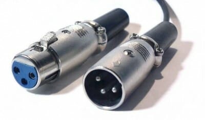
XLR connectors :
In the case of an XLR cable, the three wires are called, X (ground), L (left, hot) and R (right, cold). There are both male and female XLR connectors.
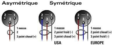
Pin 1 : Shield (G)
Pin 2 : Hot (L)
Pin 3 : Cold (R)
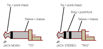
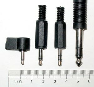
TRS connectors :
TRS stands for Tip (Left), Ring (Right), Sleeve (Shield, Ground). Although it may look like a standard 1/4″ (6.35 mm) or 1/8″ (3.5 mm) phono plug, it has an extra ring on its axis. TRS cables have two conductors plus a ground (shield). A TRS cable can carry a balanced mono audio signal or an unbalanced stereo audio signal.
Common unbalanced connectors
The two most common unbalanced connectors are RCA and TS phono jack. Even XLR cables be used for transmitting unbalanced audio. Unbalanced speaker connectors are speakon, and banana plugs.
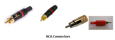
RCA connectors :
RCA connectors are associated with the RCA Corporation. Most home audio/video equipment use RCA connectors. They are even used for S/PDIF connections in digital transmission of audio signal.
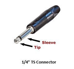
TS connectors :
There are 1/4″ (6.35 mm) or 1/8″ (3.5 mm) TS jacks. TS is the abbreviation for Tip and Sleeve. One insulator ring separates the tip and sleeve. The tip is considered to be the positive (hot) and the sleeve is the ground or shield is connected. The most common applications of TS cables are in guitar or line-level instrument connections.
Comparison of TRS and TS jacks
TS and TRS connectors look almost identical. Some equipment accept a TS connector in a TRS socket, but it may be a good idea to check the equipment documentation to be sure. Remember that 1/4″ TS connectors connect to –10 dBV line level equipment, whereas 1/4″ TRS connectors expect a +4 dBu line level (for explanation, see the section below on balanced vs. unbalanced reference voltage levels).
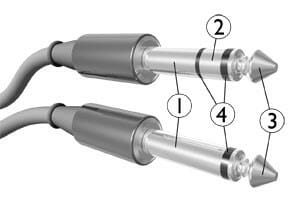
- Sleeve : Ground (Shield)
- Ring : Right channel for stereo signals, negative polarity for balanced mono signals, power supply for power-using mono signal sources
- Tip : Left channel for stereo signals, positive polarity for balanced mono signals, signal (hot) line for unbalanced mono signals
- Insulating rings
2.5 mm mono (TS), 3.5 mm mono (TS), 3.5 mm stereo (TRS), and 6.35 mm (1/4 in) (TRS) phone connectors
Phone jack connectors are available in 1/4″ (6.35 mm), 1/8″ (3.5 mm), and 3/32″ (2.5 mm) sizes. All three sizes are now readily available in two-conductor (unbalanced mono) and three-conductor (balanced mono or unbalanced stereo) versions.
If a mono TS plug is inserted into three-conductor stereo TRS socket, the result is that the right channel (ring) of the socket is grounded. The signal from the right channel will be lost. If the grounding of the right channel short circuits the right channel of the amplifier, this could damage the amplifier.
Mixing wiring configurations
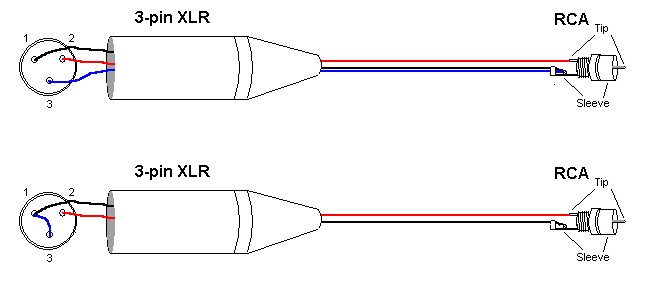
One Mono XLR Connector to One RCA Connector :
When connecting a 3-pin XLR to one RCA, the negative (-ve) and shield of the XLR are joined together, either at the RCA end or at the XLR end. The end result will be unbalanced.
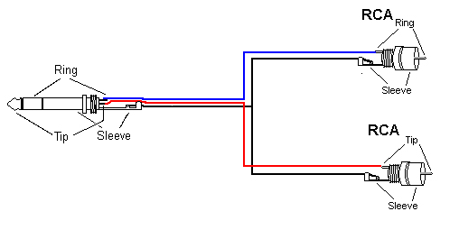
Stereo TRS Phono Jack to Two RCA Connectors :
When a stereo 1/4″ phono jack is used, the left and right parts of the stereo signal are split off to two separate connectors.
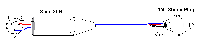
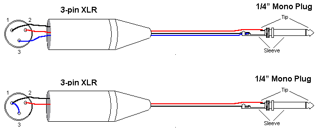
One Mono XLR Connector to 1/4″ (6.35 mm) TRS Connector:
Normally, the 3-pin XLR is connected to a 1/4″ TRS phono jack for balanced mono applications as in the following. This type of wiring will give you a balanced mono connection.
- Pin of XLR to TRS Phono Jack Sleeve
- Pin 2 of XLR to TRS Phono Jack Tip
- Pin 3 of XLR to TRS Phono Jack Ring
One Mono XLR to One 1/4″ or 1/8″ Mono TS Phono Jack :
When connecting a 3-pin XLR to one mono TS phono jack, the negative (-ve) and shield of the XLR are joined together, either at the phono jack end or at the XLR end, and connected to the sleeve of the phono jack. The end result will be unbalanced.
Advantages and disadvantages
A balanced XLR cable has three major advantages over an unbalanced RCA cable and that is why pro users prefer them.
These are the advantages :1. 1. XLR connectors are more robust. They do not come loose as easily as RCA cables. Imagine in the middle of a rock concert with lots of speakers, amplifiers, cables, and all the craziness, some RCA cables become loose. You will have a riot.
2. Because they are balanced and are grounded better, XLR cables are relatively noise free. RCA cables, on the other hand, can drive you crazy with noise and hum.
3. There is a limit on how long you can make an RCA cable (normally below 10 meters) before it significantly attenuates the signal. XLR cables can be as long as a few hundred feet.
Unbalanced RCA cables, on the other hand, have a few advantages :
1. Unbalanced RCA cables are less complicated.
2. They are less expensive.
3. They are readily available in almost all retail stores.
4. Many manufacturers include them with their products.
The biggest disadvantage of unbalanced cables is that they are susceptible to noise problems. In general, hey should be kept as short as possible.
If the signal is unbalanced out of you receiver, it will arrive that way. Using an RCA to XLR cable will not be of any advantage nor will an RCA to a balanced 1/4”. When you use a cable with an unbalanced RCA connector on one side and a balanced XLR connector on the other side, the end result will become unbalanced and you will lose all the advantages of an XLR cable. That is why the use of a converter box such (described below) is recommended.
Use of balanced/unbalanced line level converters
Balanced and Unbalanced Reference Voltage :
For consumer audio products using unbalanced RCA connectors, the reference signal level is -10dBV. This is equal to reference voltage level of 0.316 Vrms. 0 dBV is a voltage reference point equal to 1.0 Vrms. Remember that the dB level is a LOG ratio of two voltages.
=20*LOG(0.316/1) ˜ -10 dB
For pro audio products using balanced XLR connectors, the reference signal level is +4dBu. This is equal to voltage reference level of 1.23 Vrms. 0 dBu is a voltage reference point equal to 0.775 Vrms.
=20*LOG(1.23/0.775) ˜ +4 dB
When a home audio equipment with an RCA output is connected to a pro audio equipment’s XLR input, the signal will have to increase by as much as 12 dB. The casual observer would think to convert -10 dBV to +4 dBu, you would need 14 dB of gain. The casual observer would be wrong. You only need 12 dB of gain. The reason is not only do you change levels, you also change reference levels — from dBV to dBu. The first (dBV) references everything to 1.0 volt, while the second (dBu) references everything to 0.775 volts.
=20*LOG(1.23/0.316) ˜ 12 dB
As soon as you make an unbalanced connection at one end of a wire, the whole thing becomes unbalanced. So for maximum noise immunity, you should use balancing adapters.
Unbalanced lines should always be kept under 10 feet (3 meters) to prevent undesirable effects such as hum and noise. There are balancing transformers available for long runs of cables. For example, if a microphone with XLR connectors is to be connected to a prosumer camcorder, an XLR adapter should be used for converting unbalanced outputs to balanced lines, allowing for long runs of XLR cable.
MAJORCOM

Expert in Public Address and Voice Alarm systems for the past 50 years.
Our other documentation
Installation advice and information

Majorcom provide ranges of professional installation loudspeakers for indoor and outdoor PA applications …
How to measure a speaker line impedance

Impedance is a measure of the opposition to the flow of an alternating current in a circuit; the aggregation of its resistance …
Omnidirectional speakers

Recognized since 1992 and protected by an international patent, so far the omnidirectional speakers created by MAJORCOM …