
INDUCTION LOOP SYSTEMS
What is an Audio Frequency Induction Loop System (AFILS) ?
An Audio Frequency Induction Loop System (AFILS), or Magnetic Induction Loop, is a simple and effective system for communicating with hearing-impaired people. Hearing-impaired people need a hearing aid with “T” functionality (as in telephone). These aids contain an induction coil that receives the signal from a Magnetic Induction Loop.
An Audio Frequency Induction Loop System (AFILS) results in the installation of cables in the floor, walls or ceiling, which emit an electromagnetic field. This field is picked up by hearing aids.
Thanks to this system, the people concerned receive a signal emitted directly from a mixing desk, for example, so they are cleared of acoustic problems or ambient noise in the place where they are.
The result obtained following the installation of such a loop must comply with European standard NF EN 60118-4.
The Audio Frequency Induction Loop System (AFILS) is the principal means of making everything that uses sound (entertainment, fire alarms, reception) accessible to the hearing impaired, in accordance with French law no. 2005-102 of February 11, 2005, on equal rights and opportunities, participation and citizenship for equal rights and opportunities, participation and citizenship for people with disabilities, which came into force in 2015 and applies to all establishments open to the public (ERP).
Applicable regulations
- Law n°2005 – 102 of February 11, 2005
Following the regulatory provisions of the 2005 “handicap” law, France’s 650,000 establishments open to the public are obliged to make their facilities accessible, whether or not they have to undergo an accessibility diagnosis.
The aim of the February 11, 2005 law on equal rights and opportunities, participation and citizenship for people with disabilities is to raise civil society’s awareness of the need for greater justice and attention, and thus ensure better integration of people with disabilities.
Establishments Open to the Public (ERP) and Installations Open to the Public (IOP), such as administrative, cultural, health and sports facilities, are naturally concerned by the need for accessibility. People with disabilities must be able to move around and receive information without any difficulty.
- Code de la construction et de l’habitation
Article R 111-19-2
A building or facility is considered to be accessible to disabled people if, under normal operating conditions, it enables disabled people to move around, access premises and equipment, use equipment, find their way around, communicate and benefit from the services for which the building or facility was designed. Access conditions for disabled people must be the same as those for able-bodied people or, failing that, present an equivalent quality of use.
Article R 111-19-8
Provisions applicable to existing Establishments Open to the Public (ERP) or Installations Open to the Public (IOP) : they must comply with the provisions of article R. 111-19- 2.
How does an Induction Loop System work ?
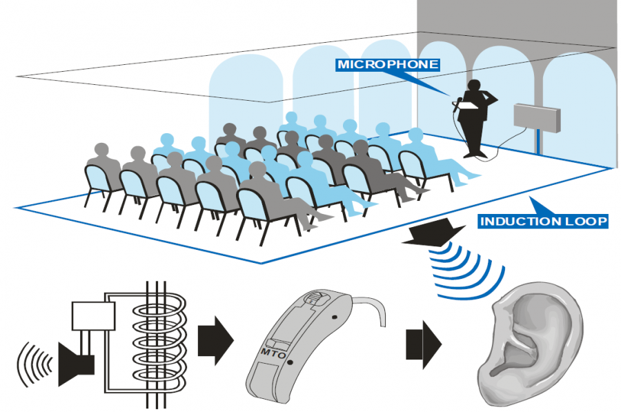
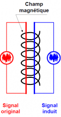
When a current flows through an electrical conductor, a magnetic field is created around it.
If another conductor is immersed in this magnetic field, an electrical signal identical to the first appears at its terminals.
This is called an “induced” signal, hence the term induction. This principle is notably used in transformers.
NF-EN 60118-4 standard
This standard defines a normalized level of maximum magnetic field intensity at 0 dB = 400 mA / m (1kHz sine signal), with a constant signal level of plus or minus 3 dB in a frequency band from 100 to 5000 Hz and for an average listening height of 1.2 m for a seated person and 1.7 m for a standing person.
Background noise (magnetic field disturbance) must be less than 32 dB.
Signs must be prominently displayed. People with hearing aids are expected to be familiar with them.
The type of site and surface to be equipped are very important, as they will determine all the guidelines to be followed in terms of :
- The type of loop cabling: “single” loop or “figure-of-eight” loop,
- Crosstalk to be taken into account or not (if adjacent but independent rooms are to be equipped, or if a microphone is to be used),
- Choice of amplifier,
- Choice of cable cross-section.
1- The surface/typology of the site
All surfaces can be equipped, but certain parameters need to be taken into consideration.
- For a room whose width is less than or equal to 15m and whose length is less than or equal to 4 times the width, a “Simple” loop can be installed :
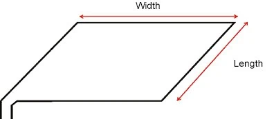
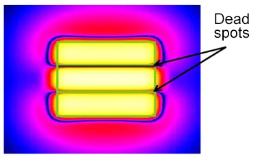
- Otherwise, a “figure-of-eight” loop must be set up :
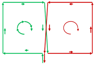
Caution : The magnetic field is cancelled out by overlaps within the loop. You must therefore ensure that this overlap is not located in a “useful” zone.
2- Crosstalk ?
If several contiguous rooms are to be equipped, crosstalk must be taken into account. In other words, the influence of one loop on another. The magnetic field does not stop abruptly. The isolation distance between 2 loops is about 1/2 the width of the loop.
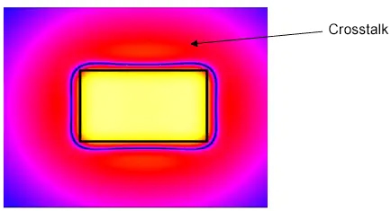
If 2 magnetic loops are installed closer together, a LOS (Low Overspill System) is required.
A “Single” loop has much greater crosstalk than an “Eight” loop.
LOS system :
A LOS system consists of 2 superimposed “Master” and “Slave” loops.
The signal emitted by the “Slave” loop is 90° out of phase with the “Master” loop.
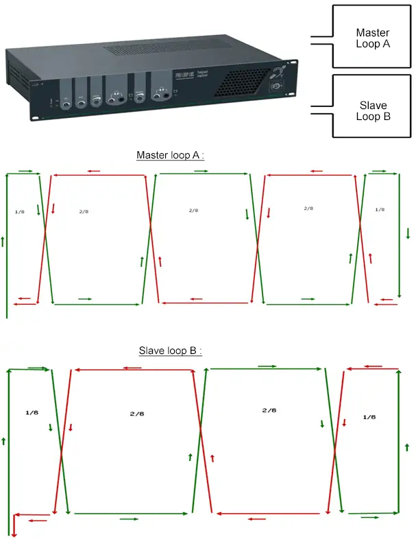
The segment width of an area (1/8) shall not be less than 0,8m.
The 2 loops will be superimposed, so the isolation distance between the 2 loops will be a few tens of centimeters:
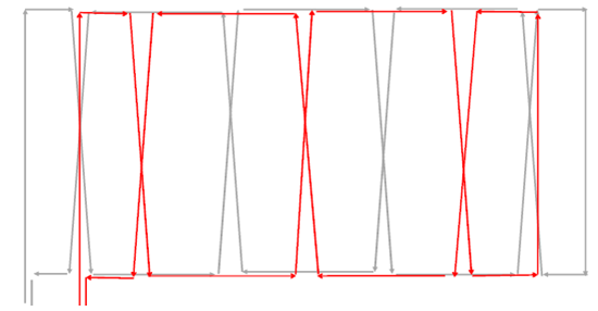
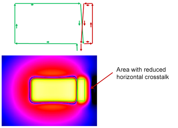
Horizontal crosstalk :
If you want to use stage microphones, in order to limit the effect of feedback on a zone, you can adopt the following principle :
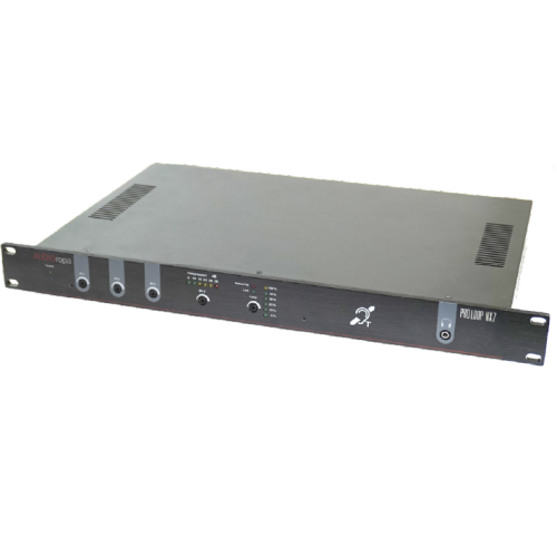
3- Amplifier
The amplifiers to be used for a Magnetic Induction Loop must comply with NF EN60118-4.
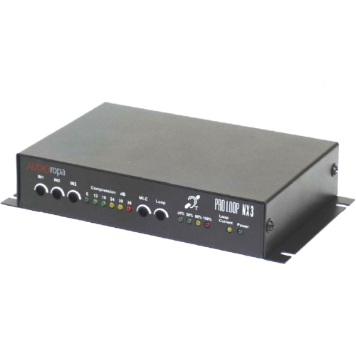
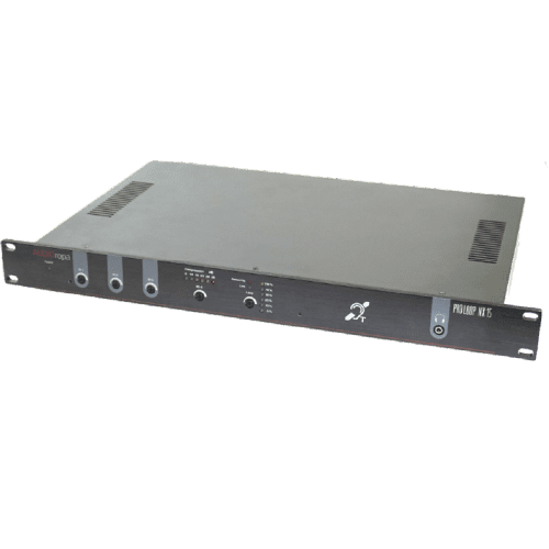
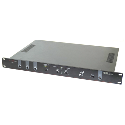
Amplifier power depends on the surface area of the site to be equipped.. Our range includes several references for coverage areas ranging from 56 to 3,400m².
PROLOOP NX7 LOS and PROLOOP NX15 LOS amplifiers are recommended when low crosstalk is required.
Induction loop cable
The cable to be used for Induction Loop Systems will be unshielded, with the cross-section depending on the surface area of the site to be equipped and the distance between the amplifier and the loop.
5- Installation
WARNING : The influence of the magnetic field (background noise) must be less than 32 dB (according to EN 60118-4 standard) to ensure good intelligibility.
Sources of interference can be :
- Transformers
- Three-phase power cables
- Electric lighting
- Nearby magnetic loops
The magnetic loop cable should ideally be laid on the floor or ceiling if it is not too high (<2m40).
The loop can be embedded in concrete if it is not reinforced. In addition, this loop must not be near metal (exclude metal cable trays, for example).
Keep the magnetic loop cable at a safe distance (min. 0.25 m or more) from other electrical cables.
The cable between the amplifier and the magnetic loop must be twisted.
6- Testing Induction Loop Systems
The magnetic fields generated by the loop are controlled by Majorcom the system is commissioned.
We use a test tool to ensure that the intensity complies with the EN60118-4 standard and that the audio signal perceived by the hearing-impaired person is correct (no saturation or distortion).
Recommended products
MAJORCOM

Expert in Public Address and Voice Alarm systems for the past 50 years.
Our other documentation
Installation advice and information

Majorcom provide ranges of professional installation loudspeakers for indoor and outdoor PA applications …
How to measure a speaker line impedance

Impedance is a measure of the opposition to the flow of an alternating current in a circuit; the aggregation of its resistance …
Omnidirectional speakers

Recognized since 1992 and protected by an international patent, so far the omnidirectional speakers created by MAJORCOM …
REFERENCES
APPLICATIONS


OUR SERVICES
Services to guarantee your satisfaction !
| Consulting | Commissioning |
| Technical study | Customer support |
| Assembly | Maintenance |
CATALOG
Find all our products, their description, and technical details in our catalog.


